programming

How to Turn Laptop Webcam into Digital Camera

AI generated image of a camera

In my last blog post, I said that I wanted to try finishing a project instead of starting a new one. Let’s forget that and kick off a new project. In my defense, I started working on this idea a few months ago already, and now I am (mostly) finishing it.

Back then I thought that it would be fun to have a retro-style camera. An analog camera would be neat, but developing films in this day and age is a bit of a pain. Early 2000s digital camera could be an option, but paying for one of those would be a bit of a waste. I mean, they cost maybe 10€, but it’s more a matter of principle. A Polaroid camera would tick all the boxes, but that idea didn’t come to my mind.

Then I thought why not build a digital camera? Well, for starters, it takes some effort that’s definitely worth more than 10€. Also, it takes some materials that are worth more than 10€. So yeah, all around a silly idea. Let’s do it.

Camera Lens

When I say that I’m going to build a camera it doesn’t mean building a lens. Those are quite precise devices, and it would be quite a bold claim to say that I possess the skills or facilities to make them. Instead, I had to salvage one from somewhere. Fortunately, every laptop contains a camera lens in the form of a webcam, and I have some spare laptops lying around. Also, the benefit of using a laptop webcam as a camera lens is that it contains a controller that can usually be interfaced with USB.

So, it’s time to get the fine-tuning hammer and give my ancient laptop a light tap with it:
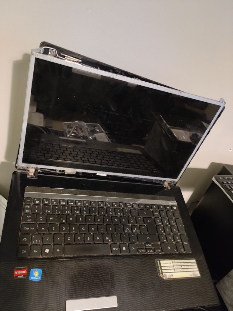
Image of a disassembled laptop
*bonk*

This process of course varies from laptop to laptop, but usually “<laptop name> disassembly” search from Google is a good starting point. There is always a small random repair shop that has made a disassembly video for your laptop. After the webcam is within reach, it’s just a matter of cutting the wires and terminating them. Not a good idea to have unterminated wires inside a laptop, at least if it’s still going to be used.

So now I have the camera module for my camera. I just need to figure out how to connect it to anything. The wires didn’t seem to follow any standard coloring scheme, and after some googling, I couldn’t find any standard order of the wires either. However, there is this useful information printed on the silk screen underneath a sticker in the back:
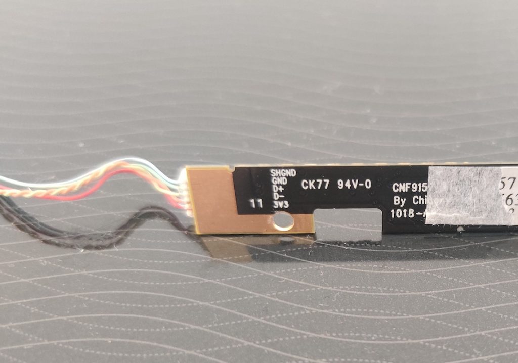
Image of a laptop webcam module with the wire labels printed on a silkscreen
I wonder what these ancient hieroglyphs mean

The next thing to do is solder the power of the webcam to the power of a USB cable, ground to ground, D+ to D+, and D- to D-, right? Wrong (maybe). I’m not sure if someone has mislabeled the wires or if I just messed them up, but soldering D+ of the webcam to D+ of the USB cable (and the same for D-) resulted in following errors in Linux when plugging in the device.

kernel: usb 4-1: new low-speed USB device number 14 using ohci-pci
kernel: usb 4-1: device descriptor read/64, error -62
kernel: usb 4-1: new low-speed USB device number 15 using ohci-pci
kernel: usb 4-1: device descriptor read/64, error -62
kernel: usb usb4-port1: attempt power cycle
kernel: usb 4-1: new low-speed USB device number 16 using ohci-pci
kernel: usb 4-1: device not accepting address 16, error -62
kernel: usb 4-1: new low-speed USB device number 17 using ohci-pci
kernel: usb 4-1: device not accepting address 17, error -62
kernel: usb usb4-port1: unable to enumerate USB device

This is where I gave up a few months ago on my first try. I was too sad to go on.

Meme that says "my disappointment is immeasurable and my day is ruined"

The Project: Rebirth

Fast forward two months. I saw an ad for a contest. The competition was looking for something that could be described as “overengineered DiWhy” projects, but maybe in a bit more positive sense. After seeing the ad, and realizing the fact that a 3D printer was available as a reward, I knew what I had to do: finish the digital camera.

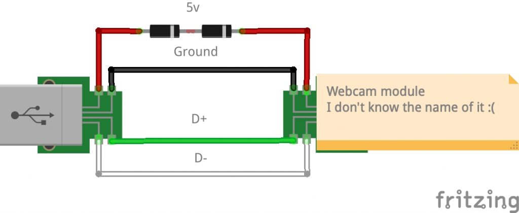
So I dug up the abandoned project and soldered D+ to D- and D- to D+, plugged the thing in, and was pleasantly surprised that it actually now worked and I hadn’t caused a heat death of the device with careless soldering. The final schematic ended up looking like this:
Schematic of the webcam module connected to a USB port
Note that D+ and D- are subjective truth in this reality. Mixing them up shouldn’t break the device but it won’t work either.

Two 1N4001 diodes are used to drop the voltage from the USB’s 5V closer to the 3.3V expected by the camera module. After reading some blog posts about similar projects it seemed like some other people had had the same problem with D+ and D-, so it may be a common point of confusion.
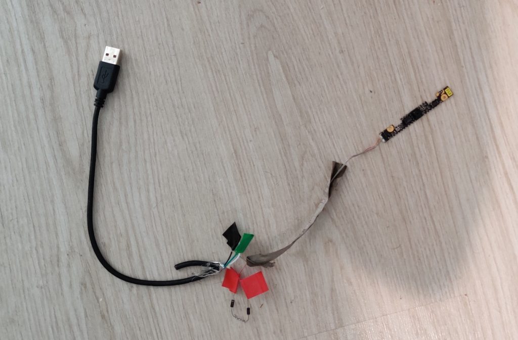
Picture of a webcam soldered to a USB cable
The quality of the connections has nothing to do with the possible communication issues.

The next step was coming up with a plan for what to actually do with this thing. I ended up using a Raspberry Pi powered by a power bank and creating a small control/status board using GPIO pins of Raspberry Pi.

Control/Status Board

I put together all my entry-level electronics knowledge and tried to remember which way the LED should be connected. I failed. After googling some basic Arduino tutorials for children, I came up with this kind of schematic.
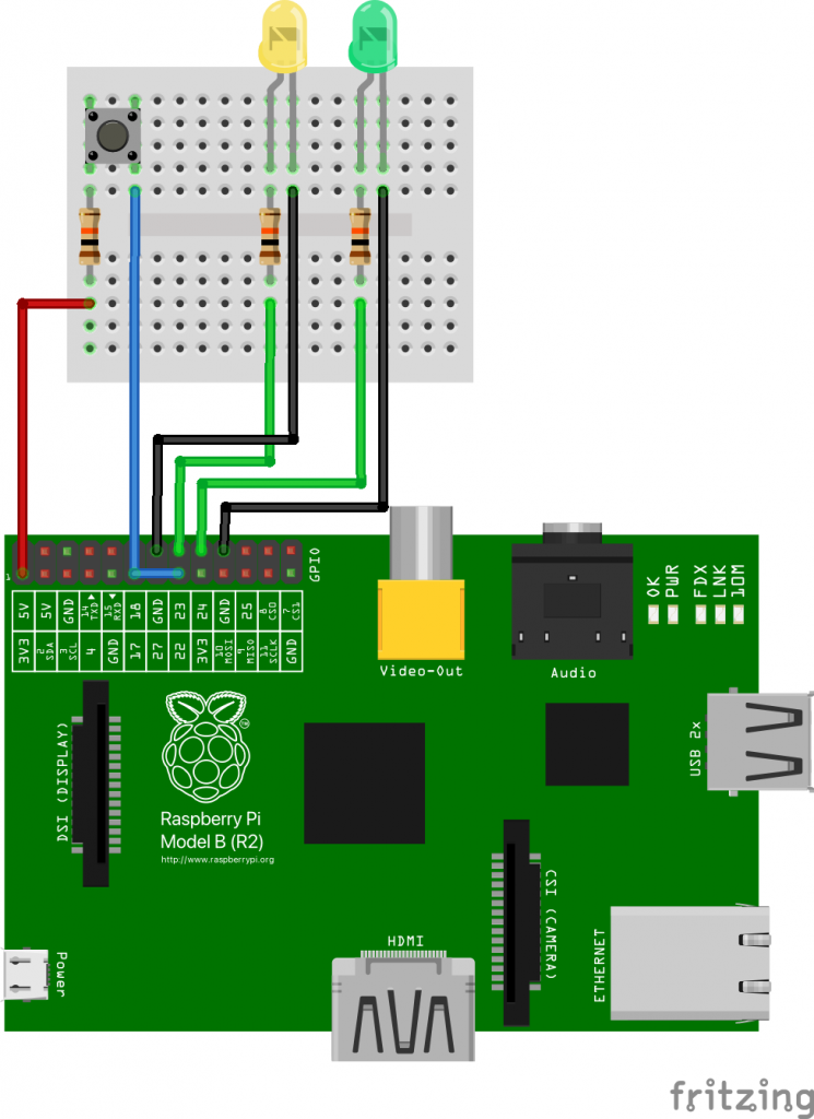
Schematic of a breadboard containing a button and two LEDs connected to a Raspberry Pi
LEDs are connected to GPIO pins 23 and 24, button is connected to 22.

To be honest, I don’t quite understand electronics as well as I would want to, and I’m not 100% sure if the resistors are the correct size. At least the board works and doesn’t produce audio-visual bang-smoke output, so I guess it’s good? Or maybe I’m slowly but steadily causing some irreparable damage that will manifest itself in surprising and slightly disappointing ways? Only time will tell.
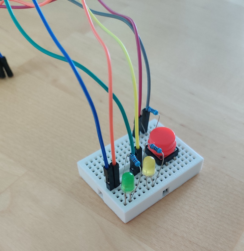
Image of a breadboard with a button and two LEDs
Can a button be anything besides big and red? I think not.

The purpose of the button is quite obvious: press it to take a picture. The LEDs give an indication of the system’s status. One LED turns on when the device is listening to button presses and ready to take pictures. The second one turns on when a picture is being taken (it’s a surprisingly long process).

I’ve Got the Power

To power up the Raspberry Pi I used a power bank that has enough juice to power up the device. It’s Anker Powercore II 10000 that outputs 5V and 3A, which is within the recommended limits. In addition, I “soldered” a switch to the power wire of the USB cable to have a rudimentary power button. “Soldered” is in quotes, because I tried new lead-free solder for the first time, and nothing really stuck on anything despite the maximum heat and effort, so it was closer to suffering than soldering.
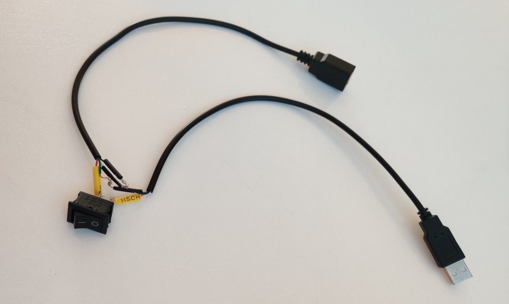
Image of a USB cable with a power switch
I haven’t tried if the data lines work, but if I had to guess, I’d say no. I’m surprised that even the power line works.

Software

This type of device could use two software components:

  1. A program that handles GPIO input and output
  2. A program that captures the camera frame and outputs the image

I wanted to write a program that would actually communicate with the camera module, but because I had to finish the camera in time for the contest, I opted for an existing solution. fswebcam is a command line software that can be used to capture frames from a webcam, which is exactly what we’re going to do.

The first piece of code I wrote is camera-gpio. It turns on the standby LED, polls the button state, and turns on another LED if an image is being taken. If the button is pressed camera-gpio launches the second program that actually takes the picture. Quite self-explanatory. It’s a C program that’s built with CMake, because I wanted to refresh my memory on how those work.

The second code repo is camera-handler, and it’s for the program that takes the photo. Currently, it’s pretty much just a wrapper for fswebcam. camera-handler also generates filenames for the images from the system time, which is a bit useless because the board doesn’t have RTC or NTP to store or sync the time. But you have to consider the opportunities, all the things it could be! It’s a C++ program that’s built with autotools, because I wanted to refresh my memory on how those work.

If you’ve been reading this blog before, you may know what comes next: Yocto build. In addition to these code repos, I made a meta-layer named meta-camera with the required files to build these into a Linux firmware image ready to be flashed into an SD card.

Final Schematic and Photos

Once all the pieces were ready, all that was left to do was plug in the thingys, boot up the thingy, and hope for the best.
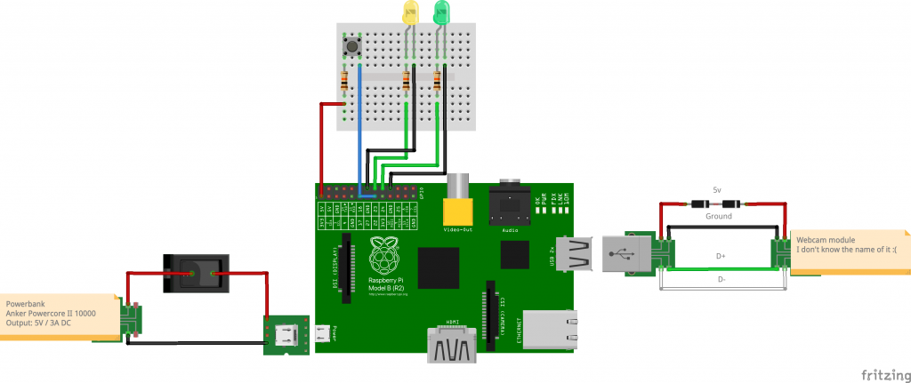
Schematic of the Raspberry Pi camera

Hope is a powerful thing. It may lead to a semi-functional thingy that takes pictures. Here’s a picture of the final build:
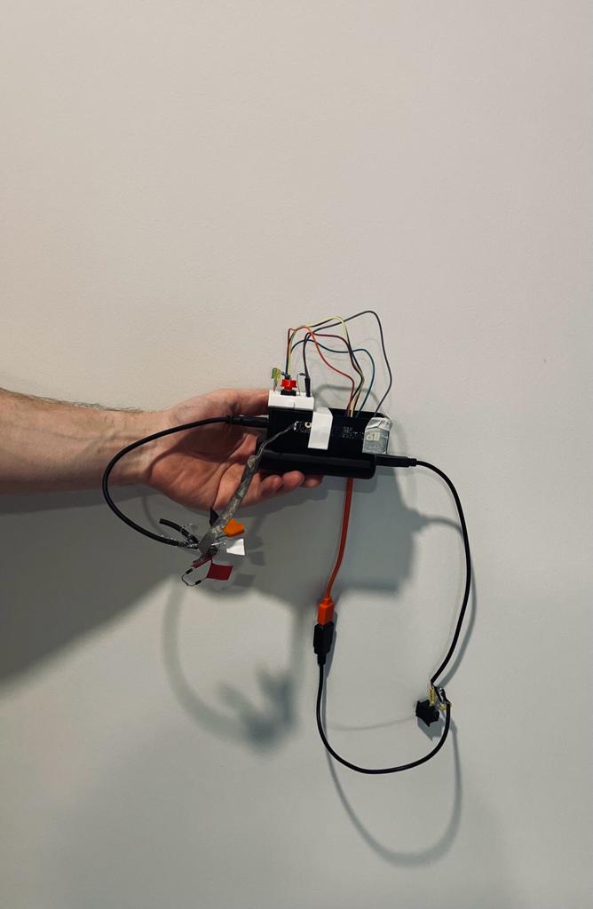
Image showing the Raspberry Pi camera
Doesn’t look quite as good as it did in the schematic. Just don’t take it with you on an airplane.

Beautiful. I posted this picture earlier on Linkedin and considered sorting out the wires. Decided to keep them as they are, because I can’t be bothered to be honest.

How do the actual pictures look? Well, I’m going to be polite and say “quite retro”, which was the original goal of the project. See for yourself:

Image taken with the Raspberry Pi showing two decorative pigs
“Coffee break of the piggies threatened by a long-legged spider”
Image taken with the Raspberry Pi showing a forest
“Sunrise in Suburbia (picture taken at 13:02)”
Image taken with the Raspberry Pi showing a close up of a leaf
“Oh wow didn’t expect this close-up to actually look tolerable”

At the least the file sizes are small.

Future Work

Honestly, I think this project could still use plenty of work. Here’s the list of things that could be fixed or improved:

  • Make the boot-up time shorter: While it’s delightfully old-school to wait 20 seconds for the camera to start up, it’s also a quite nerve-racking experience to wait every time for almost half a minute to see if the device still works.
  • Make the picture capture time shorter: It takes quite a few seconds to take a photo. Well, taking the picture itself is almost immediate, but using fswebcam is quite slow.
  • Store the pictures on their own partition: Currently, images are stored in the boot partition because that’s where they can be easily accessed. This is a hilariously bad idea for multiple reasons.
  • Audio feedback: It feels weird to use a camera that doesn’t make an artificial shutter sound.
  • PTP device: Currently, the SD card needs to be removed from the camera and inserted into a computer to access the images. It’d be nifty if the device could just be plugged into a computer to browse the photos.
  • Fix kernel issue at boot: Oh, did I forget to mention that there’s a kernel error message printed during boot? Well, there is. And it should most likely be looked at.
  • Create a nice case for the camera: I wish I had a 3D printer to print a case for the camera. I wonder where I could get one. *wink wink nudge nudge*

All in all, I think there are more things that should be done than actually have been done. However, I’m also quite happy with the things that are already done. Good starting point for whatever comes next.

Image taken with the Raspberry Pi showing overexposed light
“The future is bright (and full of overexposure)”

Delayyyyyy: v0.1.0, The First Release

Time for a celebration! The 0.1.0 release is here. It took quite a lot of effort to get everything in place and tested. As usual, the last mile turned out to be more difficult than expected. But in the end, things finally felt good enough for the first beta release. I broke the philosophy of having only one logical change in a single pull request by stuffing all the final changes into one PR, sorry about that. In this blog post, I’m going to go briefly through those commits that lead up to the beta release. The section headers are links to individual commits in case you want to judge my code.

Fix bug in short BPM synced delays

So, first things first, the cliffhanger I mentioned in the previous blog post: the bug in the synced delays. The bug was that when there is a high amount of echos, but not enough synced time signature values for them, the plugin went quiet. Instead, there should have been the few short echoes that were available, but still less than the specified amount. This was caused by prematurely breaking out of the loop that creates the delay buffers. Breaking out of the loop would have been fine if we would have been incrementing the iterator (i.e. creating the longest delay first). However, the loop iterates in reverse order (i.e. creating shortest delay first) and thus we can’t break from the loop before going through all synced time intervals.

It may not be a good idea to lie to the user about the final number of echos though.

This is how I imagine an average user.

Fix parameter state storage

I finally tried a simple saving of parameters in a digital audio workstation project. As it turns out, empty functions don’t do much of saving (or loading), and when I reloaded the project the carefully set parameters were gone. The solution was simple, actually it only consisted of copy-pasting code from an official JUCE tutorial. Not only for the saving but the loading as well. One feature isn’t much of use without the other.

Get BPM from a possible VST host

This is the big one. Basically, I did the following things to achieve this:

  • Run setDelayBufferParams in it’s own thread
  • Read BPM (beats per minute) from the playhead object
  • Detect if BPM changes

The first change was done out of necessity to make the second change possible. Playhead is an object that contains audio playback information, like the position of the audio track or the BPM (if available). However, this object can only be read in the processBlock-function. I can’t remember if I’ve mentioned this earlier, but processBlock-function should execute as quickly as possible to keep audio latency as small as possible.

So, we can’t run setDelayBufferParams in the processBlock because we want to keep things smooth. Instead, a separate thread needs to be created and notified in case the BPM (or any other parameter) changes. The thread also checks parameters every now and then by itself. For thread control, I tried to make a sort of one-sided locking where setDelayBufferParams always waits for the processBlock to finish (even if it’s not running, because it’ll run soon anyway), and then hopefully run before the next block has to be processed because the processBlock is a really busy function and it has no time to wait for anything or anyone.

However, thread-control based assumptions that things “should definitely work this way” will fail with 100% certainty. This is no exception. I’ll fix this in a future commit, but please keep this silly design in mind (and then forget it so you won’t create it yourself)

Add plugin header and version info

What’s worse than getting a bug report? Getting a bug report without the version information, or even the name of the product. This commit added a neat little header that shows the name of the plugin, the name of the creator, and even the version in the bottom right corner. I should have dropped the name of the creator though, so no one could send me bug reports.

This commit uses a neat UI feature of JUCE: removeFrom. This can be used to crop (and return) a certain section of the screen area. Something like this is perfect for the headers. Just remove a bit from the top, and the removed area is the new header area! No need to break the existing flexbox-based UI to try and fit header info in there.

Remove negativity, add Fonzie and update TODO

Does what it says, all changes here went to the README. There may be better issue management tools than just updating the README, but at least it’s not as bad as JIRA.

I have watched zero episodes of Happy Days in my life, hopefully I’m using this correctly.

Set the initial values of parameters to default values

This commit sets the initial values of the parameters to their default values. Would you have guessed? Basically makes the code a bit neater. However, this introduced a quite big bug that I somehow missed: the plugin makes no sound before the UI elements are edited because the delay buffers only get created if the parameter values change. If the parameter values are initialized to their default values, the buffers won’t get created before UI changes to something non-default. This programming bug is equivalent to a fist-sized cockroach in real life. I reverted this change here shortly after merging it, but I may need to revisit the idea some other day.


And then I thought that I was ready for the 0.1.0 release. I did some final testing of the plug-in, fiddling around and making sounds. Life was beautiful. Until suddenly, a deafening “pop”-sound occurred. Ableton recorded it to be 173 dBFS. Fortunately, I wasn’t using my headphones, otherwise my head would have exploded. People from miles away heard the sound of my mistake, which was slightly embarrassing.

Fun fact: the loudest sound on earth has most likely originated from the Krakatoa volcano eruption in 1883. It was recorded to be 172 decibels 100 miles away. And that’s probably the most educational thing in this blog so far.

Well, the reality is a bit less exciting to be honest. The sound wasn’t that loud, and I guess Ableton just calculated it “a bit” wrong. But there was a pop, and it was reproducible easily: just by wiggling the controls of the plugin for a minute or two.

And this is where my “slightly” “stupid” approach to thread control comes in.

Fix race-condition in setDelayBufferParams and processBlock

Basically, it’s dumb dumb very very dumb to assume that some things can and will always run in a certain time frame. In the end, it’s better to have a bit more latency than weird popping audio artifacts. Basically, the sound occurred when setDelayBufferParams didn’t finish before the processBlock was called. As you remember, processBlock waits for no one. So setDelayBufferParams was happily replacing/removing the delay buffers and processBlock was happily reading those garbled memory locations, and a pop sound occurred. That’s why I added a wait to the processBlock so that it won’t run too early. Not the best possible design, but it’ll have to do for now (and most likely until the end).

Add companyName for VST information

Finally, while testing out the plug-in I noticed that the company name wasn’t set correctly (it said yourcompany or something like that), so I fixed it to point to my musical alter ego.

And that’s it! That’s the story of how 0.1.0 came to be. I made one final PR where I added the ready-built x64 VST3-file and updated the README with the known issues of the plugin being a CPU hog and popping occurring while editing parameters. The CPU optimization is worth another story, but I already have a few ideas for that (and for the popping as well). But meanwhile, you can download the VST3 plugin here:

Delayyyyyy_0.1.0 release

This is how it feels to optimize. Even the quality of the GIF is optimized.

Delayyyyyy: BPM synced delay effect

As a hobby project, I have been working on a VST plugin lately. For people who are unaware of what a VST plug-in is (I assume this is most of the people), it’s basically an audio effect or instrument used with DAWs (digital audio workstations). To simplify the concept even further, it’s a piece of software that either creates or modifies an audio or MIDI signal.

The plugin I’ve been working on for the past few months is an audio delay/echo plugin. It takes an audio signal and repeats it a given amount of times with some certain maximum delay value. It also has few simple options: decay time for deciding how quickly the repeated signal levels decay, and a “ping pong” to alternate the left and right sides of the signal.

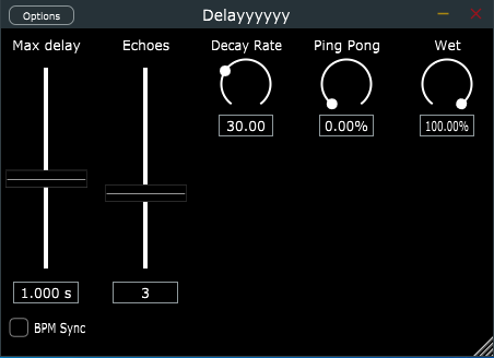
Ta-dah! This how the plug-in looks at the moment.

Now that I’ve briefly explained what the project is about, I can talk about my latest addition to the plugin: BPM synced delay (basically a delay that is synced to the rhythm of the music). I’ll admit, this may feel a bit like jumping into a moving train when there’s existing code that hasn’t been explained in previous blog posts, but I’ll try my best to keep this simple & understandable. Here’s a link to the PR that contains the BPM sync feature I’ll be talking about in this blog post.

There are changes to two classes, PluginEditor and PluginProcessor. The former is responsible for the UI, and the latter for the actual signal processing.

In the PluginEditor changes were quite simple. I added a BPM sync check box that toggles the visibility of the synced and unsynced delay sliders. I actually had most of the stuff already in place, just commented out (commenting out code is definitely the best method of version control, trust me on this, I’ve had “senior” in my title for three whole months /s). Checkbox’ value is also used in the PluginProcessor side to see if the delay should be synced or not. I’m using CustomSliders to have a custom look and feel on the sliders, but everything should work on a regular slider class equally well (or even better).

There are also some UI gymnastics going on to get everything aligned correctly. The UI should be resizable (kinda), which causes its own headaches there. Possibly the most interesting thing is the custom textFromValueFunction that allows showing musical time signatures instead of raw slider values in the slider value box. Besides these, I also had to inherit the Button listener to be able to update UI and delay parameters whenever the user would click the button. There are more elegant ways to do this, but I think for two lines of code in a hobby project this is a sufficient solution.

Lazy day every day

Simple so far? Well, things should get a bit more interesting (i.e. complicated) in PluginProcessor. First of all, I had to create parameters for the synced delay toggle and synced delay amount to ValueTree. ValueTree is a class that, you guessed it, stores different values and helps handling them.

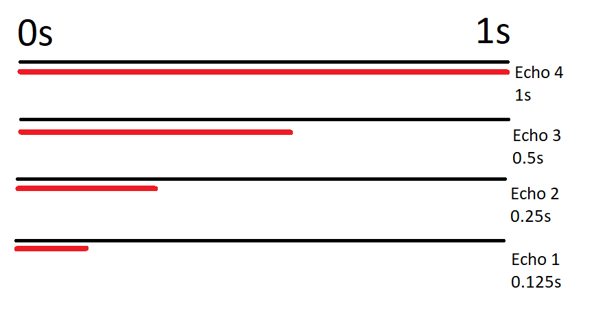
However, maybe the most important functional changes in the PR are to the setDelayBufferParams-function, and that could definitely use some explanation. The delay in this plugin works by creating a vector of size N, where N is the number of echos that we hear back. This vector is then filled with ring buffers, and these buffers have read and write pointers that are offset by a certain amount from each other. There’s a picture after this, and I hope that it’ll explain the idea better than two chapters of words and poorly thought-out mathematical formulas.

The offset between read and write is calculated from the maximum delay time X and echo amount Y user set from the UI. The first buffer gets a value of X/(2(Y-1)), second X/(2(Y-2)), and so on, until (2(Y-n)=0. In that situation, the last buffer just gets the value X. This creates an interesting (yeah for sure) non-linear, yet fairly symmetrical delay effect. Please note that the first echo buffer has the smallest offset between read and write pointers.

ANYWAY, after this offset is calculated, the write pointer is set to this value while the read pointer is set to zero. When there’s an audio signal coming in, there’s first a read performed on the buffer to obtain the possible previous, delayed signal. Then the incoming signal with possible ping pong and decay applied is written to the buffer. Finally, the earlier read value is added to the incoming signal. This is then repeated for all the buffers. Since each buffer has a different, bigger than zero offset between write and read pointers, the audio signal gets repeated at different intervals, creating a delay effect. Wowzers!

In this example, the maximum delay is set to one second, and there are four echoes. I’ve been told to never apologize using Paint in explaining things, but hopefully this makes sense.

Now, how does this idea work in a rhythmically synced world? Well, time for a little music theory for a change. 97% of the modern western music is in 4/4 time signature, meaning that there are four kick drum hits in a bar, and music is constructed of building blocks with a size of four bars (gross oversimplification, but I don’t want to end up neck-deep in music theory because I’ll explain it wrong). So in a track with a BPM of 120 there are 120 kick drum hits in a minute, and 30 bars in a minute.

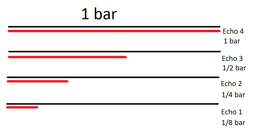
This gets a bit subjective from here, but I personally like synced delays to be divisions and multiples of two from the previously calculated value, starting from 1 bar, to create a nice rhythm that sounds good on most music. This means that the delay gets values like 1/2, 1/4, 1/8, and 1/16 when going shorter than one bar, and values like 2, 4, 8 & 16 bars when lasting longer than one bar. When we know the beats-per-minute, or BPM, it becomes fairly trivial to calculate the write and read pointer offsets that are rhythmically synced. Instead of using the user set value for the maximum delay, we calculate the time for a certain amount of beats in a certain BPM.

Looks similar, doesn’t it? Max delay set to 1 bar, and echoes to 4. The difference is that the duration of the delay doesn’t depend on the time, it depends on the tempo of the music

Hopefully, you’ve understood what I’ve tried to say with this. To make this code change slightly more confusing, there are some optimization changes thrown in there as well. Basically, earlier I had a static 10-second size for the delay buffers. However, with synced delays, this may not be enough, and for the shorter un-synced delays, this will be way too much. So I set the buffer’s size to be equal to the write pointer offset because there is no point in having the buffer be longer than that. The ring buffer will rotate more often, but that isn’t really an issue because old values are not needed.

And that’s the process of how I did the BPM synced delays to my VST plugin. The theory is quite simple once you get the idea of how I implemented the delay buffers, after that it’s just a matter of modifying the write pointer offset. The rhythm is still hardcoded to 120 BPM, but it’ll be fixed in the next PR. There’s also one bug in this implementation that I’ve fixed on my local branch already, but I’ll leave details on that as a cliffhanger to my next blog post.