tutorial

Making USB Device With STM32 + TinyUSB

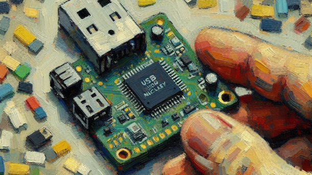
Have you ever wondered how USB devices are made? I sure have. It’s interesting how you can plug in devices using the same type of connector, and the devices work on (almost) any machine and you can get wildly different functionality from them. There are USB sound cards, network adapters, mass memory storages, oscilloscopes, table fans… The list goes on. The only limit is your imagination and five volts.

Introducing coffee cup warmer 3.0. It mines crypto (for me), and uses the generated heat to warm a coffee cup (for you). It’s win-win. And look, it even has a light so that you can drink coffee (and mine crypto) in the dark.

However, creating such a device seems like a big undertaking. There’s the device firmware that needs to be written, and the host side driver for the device, and the USB protocol itself is notoriously difficult to understand. However, with a good USB stack, code examples and some luck the task becomes a lot more manageable. In this blog post, I’m going to port a simple example from the TinyUSB stack to the STM32F446RE Nucleo board. I assume you have at least some basic understanding of USB and that you have completed at least the blinky project on some Nucleo board.

Mandatory Overview of USB Stuff

The first thing to always learn is the basics of the theory. However, if you’ve already tried understanding the USB protocol, you may already know that it’s not as trivial as “plug-n-play” under the hood. The spec is long, confusing and scary. I’m not going to say I understand it, and I barely even understand what’s coming up in the next chapters. But configuring these things is more or less required for getting the firmware code working, so it’s good to have some understanding of the fundamentals.

USB Host & USB Device

This is a fairly straightforward chapter, but written just to make sure that I’m correctly understood in the later chapters: USB devices connect to a USB host. In a typical scenario, the USB host is a computer, and a USB device is for example a keyboard. There may be USB hubs in between the two to increase the amount of ports in the USB host. The are also USB composite devices, which combine for example a mouse and a keyboard into a single device. Finally, there’s also a USB root hub, which is a hub in the USB host that the other devices connect to.

I’m not sure how I feel about these dark-mode graphs. Something about them just feels off.

USB Speeds

Different versions of USB specification have defined different maximum transfer speeds for the USB protocol. As one can guess, newer protocol version = faster speed. Interestingly enough, the naming also gets increasingly confusing over time.

  • Low Speed (USB 1.0/1.1) [1996]
    • Data Transfer Rate: 1.5 Mbps
  • Full Speed (USB 1.0/1.1) [1996]
    • Data Transfer Rate: 12 Mbps
  • High Speed (USB 2.0) [2000]
    • Data Transfer Rate: 480 Mbps
  • SuperSpeed (USB 3.0 Gen 1) [2008]
    • Data Transfer Rate: 5 Gbps
  • SuperSpeed+ (USB 3.1 Gen 2) [2013]
    • Data Transfer Rate: 10 Gbps
  • SuperSpeed+ (USB 3.2 Gen 2×2) [2017]
    • Data Transfer Rate: 20 Gbps
  • USB4 (USB4 Gen 3×2) [2019]
    • Data Transfer Rate: 40 Gbps
  • USB4 (USB4 Gen 4) [2022]
    • Data Transfer Rate: 80 Gbps

The speeds listed here are the maximums for each version.

Descriptors

So far so good. The descriptors are where things start to become more confusing. This chapter won’t explain all the descriptors, because there are too many of them. However, when we are writing and porting the code we need to write some structs defining the USB descriptors of the device, so it’s good to have a basic understanding of what they are.

The USB device uses descriptors in hierarchical layers to describe itself to the USB host. The topmost descriptor is the device descriptor, which contains for example vendor ID, product ID, and supported USB version. There’s one device descriptor for the device. The device descriptor also contains the number of configuration descriptors. Configuration descriptors contain for example the power requirements and the amount of interfaces the configuration contains. The driver can select the device configuration from multiple different configurations.

The interfaces are described using, you guessed it, interface descriptors. Each configuration descriptor contains one or more of these. Interface descriptor contains for example class code, protocol code, and the amount of endpoints. Finally, endpoints are defined using endpoint descriptors. Endpoint descriptor defines for example max packet size, polling interval, transfer type and data direction of the endpoint.

The simplest type of device can have one of each of the four basic descriptors. A complex device with different configuration profiles and multiple interfaces may have a lot more. And, to make matters more confusing, there are also extra descriptors. For example, there may be class code-specific descriptors (like in our example there will be), and a string descriptor that contains strings, like for example the human-readable device name.

This graph shows only the descriptors we need to define for our example device. TinyUSB stack will handle the rest of the descriptors for us.

Creating the Device

Now that was boring, wasn’t it? It’s time to do something interesting. As one can guess from the fairly complex protocol, we’re going to need a microcontroller. I have a STM32F446RE Nucleo board lying around in my drawer, so I’m using that for this project. As far as I know, most of the Nucleo boards should work for this project, as long as they have USB OTG. As a USB stack, I chose TinyUSB which is easy enough to use and integrate. Also, I made an example repository of this project that you can use to follow along if you want.

About TinyUSB

TinyUSB is a cross-platform USB stack, suitable both for USB devices and USB hosts. It supports power management, multiple device classes, and is thread- and memory-safe. Especially the latter two are big promises. ST also provides their USB stack for their devices. However, I usually prefer to use solutions that are not vendor-specific. For example, if we would like to change the hardware from STM32F4 to Rasperry Pi Pico, it’d be a lot easier with TinyUSB. Granted, it may not necessarily be perfectly optimized for all of the devices, but having portable code and transferrable knowledge is always good.

Configuring Project and STM32 Nucleo Board

First, we’re going to integrate TinyUSB and configure the Nucleo board in the STM32CubeIDE. We are going to follow the instructions from this GitHub comment. Big thanks to the person who made it, this step would have been a nightmare otherwise.

I’m using STM32CubeIDE version 1.15.1, so the TinyUSB integration steps below apply to that version of the IDE. I’ve also tried this on version 1.9.0 and TinyUSB seems to work with that version as well, but some labels and menus may have different texts, so keep that in mind if you’re using some other version of the IDE.

The first thing to do is to create a new STM32CubeIDE project and set the target board. In my case, it’s the F446RE. The rest of the defaults (C project, STMCube target, etc.) should be fine.

The next step is adding the TinyUSB stack. This consists of adding headers and sources. First, clone the TinyUSB repository to some location where it doesn’t get added to the build sources automatically. I created Libs folder at the root of the project and cloned the repository there. After that is done, add the src and hw include folders to the project and src as the source folder by right-clicking the project in the project explorer and setting them in the project properties.

Here’s how the includes should look like…

…and here are the sources

Then, we can configure the chip. Open the chip configuration ioc-file, and from the menu open Connectivity->USB_OTG_FS to set up the full-speed USB port. There may be USB_OTG_HS option as well, but the high-speed USB requires an external PHY (unless you have F7 board). OTG_HS can be configured as full speed, but let’s just stick to OTG_FS. As a side note, I find the name “full speed” ironic considering that the “maximum full speed” is less than 3% of the “maximum high speed”.

I digress. Once you’ve selected USB_OTG_FS, set the “Mode” to “Device Only”. In the Configuration window below the Mode window, under NVIC settings, enable “USB On The Go FS global interrupt”. Finally, double-check that the ST USB middleware is not enabled. Scroll down the menu, select “Middleware”, and make sure that USB_DEVICE and USB_HOST related middleware is set to “Disabled”.

USB configuration is now done, but you may still need to open the Clock Configuration tab to resolve clock issues. Just open the tab, click “Resolve Clock Issues”, and hope for the best.

USB config should look something like this.

Generating the code after integrating TinyUSB has one irritating side effect: it opens main.c of all the TinyUSB examples, resulting in quite a few new tabs being opened in the IDE. I’m not sure how to fix this. I can just say that this happens.

Wiring

Wiring is simple. It consists just of connecting the relevant Nucleo headers to a USB connector with jumper wires. If you don’t happen to have a spare USB connector, you can salvage one from a USB cable.

To power the board you can either use the power from the USB host coming through the USB connector, or you can plug in a cable to the Nucleo’s USB port. For development and debugging purposes, I’d recommend using Nucleo’s USB port and leaving out the power wire because Nucleo port is used for programming the device. However, the schematic below shows how to power the board using the USB connector because it’s a bit more complicated.

Notice that if you’re using the Nucleo’s USB port to power the board, the U5V rail needs to be active, and if want to power the board with your custom USB connector, the E5V rail should be active. Active rail is controlled with the jumper visualized with a blue wire in the schematic.

Making full use of that $8 Fritzing license by creating the second schematic this year.

If you’re facing issues with the USB enumeration, for example if Windows complains that the device could not be recognized, try swapping D+ and D-. The usual mistake is to get those the wrong way around, and then wonder for too long what could be the issue. To me, it feels like these are always printed incorrectly on the silkscreen, but I’m not sure how many times I can still use that excuse.

Here’s a picture of the final product. In this setup the USB connector can be plugged into a computer and the USB host is used as the power source. It’s perhaps worth noting that the pin layout of my connector is different than in the schematic above.

Code

To summarize, programming the firmware consists of the following tasks:

  • Writing the TinyUSB configuration header
  • Writing the USB descriptors
  • Replacing the ST USB interrupt with the TinyUSB USB interrupt
  • Adding TinyUSB setup and device task functions
  • Programming the functionality of the USB device

It doesn’t make sense for me to go through these steps line-by-line, so you can check out each point from the example GitHub repository. However, I’ll go through each step on a higher, more hand-wavy level. Most of these steps rely heavily on copy-pasting the relevant code from a TinyUSB example. In this project, we are using the CDC dual ports example.

The CDC Dual Ports example demonstrates a CDC class USB device that creates two serial ports. Users can then write into either one of these two. One of the serial ports will output the written characters in lowercase, and the other port will output the same characters in uppercase.

Device class is a standardized definition that categorizes devices based on their functionality. CDC stands for “Communications Device Class”. While we’re not creating a device providing typical CDC functionality (e.g. network card, modem, fax), we can use the CDC class to easily create a serial port because that’s what devices in that class typically use for communication.

Let’s now start going through the steps. Note that the headings are links to the relevant commits.

Configuration Header

The heading is quite descriptive of what happens in this step. We need to configure the TinyUSB with the chip we’re using, the root hub we intend to use, the mode of the root hub (host or device), the maximum supported speed, etc. In our F446RE board, the full-speed USB OTG is the root hub number 0.

To write the configuration, we can pretty much copy the configuration header tusb_config.h from the example, add the fields from the GitHub answer linked earlier, and replace the root hub number, USB speed and chip with the values applicable to our project. You can diff the configuration in the TinyUSB example and my example to see what exactly was changed.

USB Descriptors

Time for the infamous USB descriptors. Actually, this is a lot simpler than I made you believe earlier. We can simply copy the usb_descriptors.c from the example folder to our project source folder. Of course, if you were writing a USB device from scratch this step would involve more work to get the device to appear correctly to the host. I still recommend checking out the commit and trying to understand what each of the structs does and contains, as they should make (some) sense after reading about the USB descriptors.

USB Interrupt

This is an easy one. Open the file containing the generated FS USB interrupt, add a call to the TinyUSB interrupt handler, and return early to avoid calling the ST USB interrupt—literally two lines (and one include).

TinyUSB Setup and Task

Before the main code enters the main loop, add tud_init call, and in the main loop call tud_task. tud stands for “TinyUSB Device” (or so I assume). Some examples have functions with tuh prefix, and these are host-related functions, so I’m guessing that is the meaning of the last letter. There is also a generic tusb_init for initializing both device and host. Discussion about the differences between the two can be found here, but to summarize tud_init is a more flexible and newer way of doing the initialization.

Note that TinyUSB and examples have an initialization function called board_setup. We are not going to use that, because the initialization code generated by CubeIDE handles the board setup for us.

Programming Functionality

The actual functionality should be the hardest part. Or at least it would be if we were making an actual device from scratch. Since we’re using a ready-made example, we can just copy the functionality we desire from the example to our project.

The functionality we want to copy over from the example contains one task that is to be run in the main loop, and a few callbacks. Quite simple, especially since TinyUSB abstracts a lot of the hardware stuff away. All we have to do is read and write the serial devices in a fairly typical fashion, nothing too USB-specific is required at this stage anymore.

Of course, this step varies wildly depending on what you’re trying to achieve. But, in our humble example project the commit enabling the functionality is quite small and easy to understand.

Testing the Device

After doing the hard work of copying the code and flashing the board, you can plug your USB connector into a computer (don’t do it on your most expensive gaming rig though, better be cautious). At least on Windows, the device should get recognized, and two new serial ports should be added to the system. If you open the serial ports (baud rate 9600), and write to one of them, you should see the input text magically appear in the other one as well. And it’s all upper- or lower-cased!

But what about the driver? Why does the device work without a driver? Well, since we are creating a CDC class device, we don’t need a special driver for it. The generic CDC driver from the operating system is used for driving the device. With more specialized functionality where we couldn’t use (or wouldn’t want to use) a device class for defining the device a custom driver would of course be required. Maybe writing a driver like that is worth a text of its own.

I’m just joshing, it’s all fun stuff. In a kind of masochistic way.

But for now, you should have your first USB device up and running. Not one of the easiest projects, but considering the complexity of the protocol it was in the end quite simple. Big thanks for this go to the TinyUSB project. Also, thanks to the GitHub answer I linked above as it was a massive help with getting familiar with the TinyUSB and STM32. I’m not sure if this text would have even happened without it. That’s all for now, thanks for reading.