
FPGA, one of life’s big mysteries. It’s like hardware, but it is also kind of like programming. FPGAs are quite common in the embedded world, and I have encountered them a numerous times in various projects. However, I have never really developed an FPGA full-time. In professional environments, there has always been someone smarter than me who’s done most of the development, and in the hobby project world, it’s been surprisingly difficult to find both an interesting and useful FPGA project. Ideally, I’d like to do a project that would combine both FPGA and SoC device, and they would do something fun together.
Commonly these kind of projects are done with SoC-FPGA boards, devices that combine both SoC and FPGA chips on the same chip. But I don’t have such a device and they cost money. Then it hit me: I already have a Raspberry Pi 5 and Basys 3 that I can use, so why not figure out how to wire these two boards together and do a small demo with them? This way I can have a kind of a SoC-FPGA board for studying further without using a single euro. I’m not sure if this interesting or useful project that I wanted, but it’s the thing that I’m going to do.
FPGA
Now, before going deeper into this, I guess it’s worthwhile to go through what an FPGA is. FPGA stands for “field programmable gate array”, and it is a chip that consists of programmable logic blocks and reconfigurable interconnects. In simpler terms, it’s programmable hardware. The benefit of the FPGA is that it is programmable (it’s literally in the acronym), meaning that it is great for prototyping hardware ideas. They can also be used for platform-specific, complex tasks with high-speed requirements that may be impossible to satisfy with the main CPU. FPGAs are also useful for situations that require a low-latency response, because the FPGA can be programmed to respond directly with the hardware implementation, without the need for software or an inefficient CPU.

Sounds good. Do you need an FPGA then? Most likely not. Usually, it is easier and cheaper to try to solve the problems using software. However, if the software solutions are not efficient enough, an FPGA is something that can be considered. This happens surprisingly often, at least in the industrial sector, when working with the embedded devices that have strict timing requirements. Some alternatives to FPGA are ASIC (application-specific integrated circuits), GPU (graphics processing units), and DSP (digital signal processors). Each of the options has its pros and cons in terms of processing power, flexibility and price, so it’s good to do research before making the hardware choice.
Creating the FPGA Demo
Let’s get to the fun stuff. But first, let me preface this chapter with a disclaimer: despite being exposed to the FPGAs for years, I’m still mostly firmware/software developer. Therefore, the demo code may contain some “silly stuff”. The code has been reviewed by a person who knows FPGAs and Verilog, so the worst mistakes should be cleaned from the code, but still. I also used help from AI to get it done. I guess that’s a given these days, but I just wanted to mention that as well. This is not vibe coding, this is vibe hardware designing (although I guess the review kind of ruined the vibe).
As mentioned in the prologue, I’m going to be using a Basys 3 board, but the code should be generic enough to work on other boards as well. Just note that the constraints file is board-specific and may require some tweaking if you’re using a different board.
Links to the Important FPGA Tutorials
I’m not going to cover how to get started from scratch with the FPGA, as the Internet is full of good resources on how to program the first blinky to an FPGA board. However, I can point you in the correct direction if you’re using a Basys 3 board like me (or some other board from Digilent).
First, you’ll want to follow these instructions to install Vivado and the Digilent board files. Vivado is the tool which is used to create digital circuits for FPGA hardware projects, and it is the program that is used with Xilinx FPGA chips.
After you’ve installed Vivado and the board files, you can follow these instructions to create the simplest hardware demo possible, a blinking LED. The tutorial is quite thorough and explains some of the core concepts of both FPGA development and Vivado, so I recommend going through it. While the generated hardware is quite simple, the tutorial should cover enough things to proceed with the code I’m about to present.
The FPGA Demo Code
Okay, at this point, you should have some understanding of what an FPGA is, how to create a project with Vivado, and how to program your board. Let’s get to the actual demo then.
The demo project that I’m going to create has the following functionality: the FPGA board has two pins that are assigned to be UART RX and TX. When the device receives the special command byte A5 from the UART, it responds with two bytes containing the status of the Basys 3 switches. The LEDs are used to display the status of the UART receiver and transmitter. It is a simple project, but it demonstrates two-way communication between the FPGA board and whatever the board is connected to.
Basys 3 doesn’t have GPIO pins that could be used for serial UART like the Raspberry Pi does, but the PMOD connectors on the side can be programmed to act as UART RX and TX pins. The PMOD connectors also have a ground pin, which is handy when connecting to the Raspberry Pi.
Without further talk, here are the source files for this demo project. The first one is the constraints file (that you may need to tweak if using a board other than Basys 3), and the second file is the actual hardware description Verilog file:
UART
In case you aren’t familiar with UART and the Verilog file seems confusing, here’s a simplified summary. UART is a point-to-point serial communication protocol that requires two data wires (one for transmitting, another for receiving) and a ground wire. There is no clock signal, instead, both ends of the communication line have to be pre-configured with a correct clock rate (and other settings). In UART, the transmitter holds the line high. When it wants to send something, it first pulls the line down for one clock cycle to signal transmission start. Then the transmitter transmits (usually) one byte. After transmission, the line is held high for (usually) one clock cycle. Once the stop bit is signalled, more data can be sent, or the device can start idling.
This explanation skips some details (like parity bits) that are not used in this demo. You can find a more comprehensive explanation with pictures from the recommended reading section at the end this blog text.
Creating the Raspberry Pi Side of the Demo
The Linux side should be more familiar territory (at least for me). For the Raspberry Pi, we need to do two things. First, we’ll need to enable the GPIO UART and hook it up to the FPGA board pins that were configured as the UART TX & RX. Second, we’ll need to write a program that sends the command byte over UART and reads the two response bytes.
Unfortunately, enabling the UART on the Raspberry Pi seems to depend a bit on the exact version of the board you have. Regardless of whether you’re using the regular Raspberry Pi OS image or a self-built image (more on that later), you’ll need to edit the config.txt file on the boot partition. On Raspberry Pi 5, it seems to be enough to add the line dtparam=uart0 to the file. With older boards, you may need to add dtoverlay=miniuart-bt or dtoverlay=pi3-miniuart-bt as well. You know you’ve been successful in enabling the serial when the /dev/ttyAMA0 device is visible on Linux.
Then, the serial communication program. This could be a fairly simple one, I wrote one with Python that should have done the trick. However, for some reason, that program never received any bytes even though the board was sending them. I even used an oscilloscope to verify this. Instead of trying to fight more windmills, I asked an AI assistant to generate a program that can perform the required actions with raw serial port communication using C for a quick verification, and that code worked.
Perhaps the implementation in Python was incorrect, or there was something weird in the Python serial library, but if you see errors when trying this out, it may be related. I have also observed a situation where the C program misses the first byte. Unfortunately, I have not been able to reliably reproduce this issue. Possibly adding a second stop bit to UART could help, but because the issue is quite rare (I’ve seen it only once), I haven’t been able to verify a fix. So yeah, it’s good to be aware that these kinds of things may be ahead with UART.
Anyways, here’s the program that can perform the required actions. Compilation can be done simply with gcc -o serial-reader <SOURCE_FILE>, no libraries required:
If you’d like to understand the raw serial communication in Linux better, I added a link to a good resource to the recommended reading section at the end.
Wiring
Hooking up Basys 3 and RasPi is quite simple, because there are only three jumper wires. Here’s a picture of the connection:
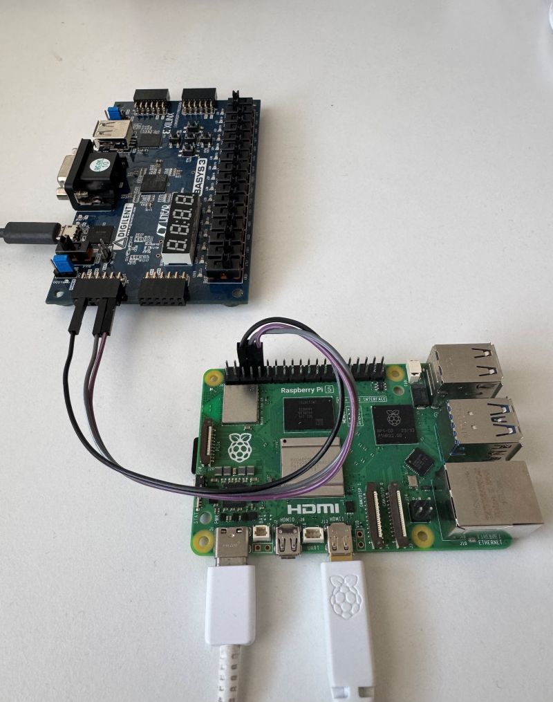
It’s perhaps a bit difficult to see from the picture, but on Basys 3, you’ll want to connect the wires to the top row of JA port. RX and TX go to the two rightmost pins, and the ground is the second one from the left. Or maybe this graph helps a bit:

Note that the USB cable of the Basys 3 goes to the computer for programming and powering the board.

Demo Time
Now, you should ensure that the Basys 3 is programmed with the correct bitstream and that you have compiled the serial communication program on the Raspberry Pi. You should also ensure that the /dev/ttyAMA0 is available on the Raspberry Pi. Once you run the serial-reader program, you should see an output that looks something like this:
Serial port opened successfully
Command byte 0xA5 (binary: 10100101) sent, waiting for response...
Response received:
Byte 1: 0x00 (binary: 00000000)
Byte 2: 0x00 (binary: 00000000)
Serial port closed
Then you can play with the switches on the Basys 3 and re-run the command. The output should be different:
Serial port opened successfully
Command byte 0xA5 (binary: 10100101) sent, waiting for response...
Response received:
Byte 1: 0x33 (binary: 00110011)
Byte 2: 0x33 (binary: 00110011)
Serial port closed
That’s it, that’s the demo. It demonstrates simple communication between a Raspberry Pi user space program and an FPGA board. Cool, isn’t it?
Custom Image & Raspberry Pi FPGA Programming
This kind of setup is good if you’re doing active FPGA development or high-level prototyping in Linux. It’s easy to reprogram the FPGA from Vivado, and it’s fairly simple to perform user space development in the Raspberry Pi as well. However, if you’re focusing on embedded Linux or complete system prototyping, this kind of setup is a bit limiting. It may be a good idea to build the Raspberry Pi image yourself, include the FPGA bitstream in the image and automatically program it during RasPi boot. This is especially useful if the FPGA bitstream is quite constant. Let’s modify the demo slightly and do that next.
New Wiring & Programming
Since we want the Raspberry Pi to perform the FPGA programming, we need to re-think the physical setup. Basys 3 can be programmed with the usual USB-JTAG, or with an external JTAG programmer. The problem is that there are no headers on the external JTAG port, and I feel it’d be a bit risky for me to start soldering them. Basys 3 also supports loading bitstream from a USB thumb drive or its nonvolatile flash, but neither of those is really what I’m looking for.
Therefore, we are left with the USB-JTAG, which means that we’ll move the USB cable from the development computer to the Raspberry Pi. Here’s the updated picture:
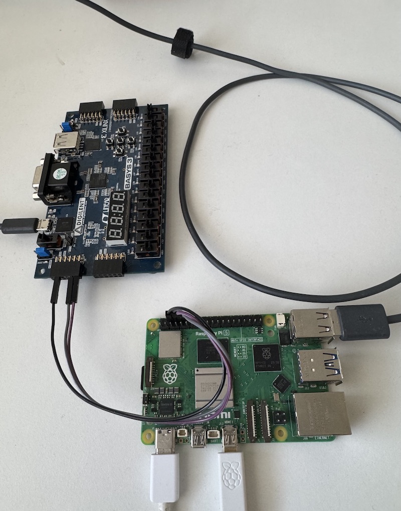
This raises the question of how we’ll program the FPGA board, since it is not feasible to run Vivado on a Raspberry Pi (it barely runs even on my laptop). Well, we’re in luck, because Digilent has a software solution named Adept 2 that can be used to program Basys 3 from the Linux command line. As far as I know, it should also work with other Digilent boards as well, but I have not verified this. Unfortunately, the program is closed source, but fortunately, there are 64-bit Linux packages available.
The tool that we are going to be using is djtgcfg, which is one of the worst-named command-line tools I’ve encountered. I think it stands for “Digilent JTAG config”, but still. The following commands can (and will) be used to list, initialise and program an FPGA board:
/usr/bin/djtgcfg enum
/usr/bin/djtgcfg init -d <BOARD_NAME>
/usr/bin/djtgcfg prog -d <BOARD_NAME> --index 0 --file <PATH_TO_BITSTREAM>
Building the Custom Linux Image
I’ll be using Yocto to build the custom image. In case you are not familiar with it, check out the quick build guide first. You’ll also need to know how to add custom meta-layers.
For this demonstration build, we’ll need to add two additional meta-layers to Poky: meta-raspberrypi and meta-raspberrypi-fpga. The first one is the semi-official Raspberry Pi support layer, and the second one is my meta-layer that contains some tools (like Adept 2) and helper recipes for FPGA work. Here are the most important files to note from my repository:
recipes-bsp/bootfiles/rpi-bootfiles.bbappend: Used to ensure that the bitstream gets deployedrecipes-example/serial-reader/serial-reader_1.0.bb: Builds the serial reader examplerecipes-fpga/adept-runtime/adept-runtime_1.0.bb: Adept runtime that is required by Adept utilitiesrecipes-fpga/adept-utilities/adept-utilities_1.0.bb: Adept utilities package that containsdjtgcfgrecipes-fpga/fpga-bitstream/fpga-bitstream_1.0.bb: Recipe that deploys the FPGA bitstream to the deploy directoryrecipes-fpga/fpga-programmer/fpga-programmer_1.0.bb: Service that programs the FPGA during the boot
Add the two required meta-layers, for example, with bitbake-layers add-layer, and then add the following lines to local.conf:
IMAGE_INSTALL:append = " adept-utilities adept-runtime serial-reader fpga-programmer"
IMAGE_BOOT_FILES:append = " fpga-bitstream.bit"
You’ll also need to enable the UART serial. At least on Raspberry Pi 5, adding these lines to local.conf is how you can achieve that:
ENABLE_UART = "1"
RPI_EXTRA_CONFIG = "dtparam=uart0"
Now, before we get to building, we still need to move a few things into place. First of all, the bitstream generated by Vivado. By default, you can find this from <VIVADO_PROJECT>/<PROJECT_NAME>.runs/impl_1/<PROJECT_NAME>.bit. Copy this file to meta-raspberrypi-fpga/recipes-fpga/fpga-bitstream/files with the name fpga-bitstream.bit. Renaming the file is important so that it gets found by bitbake.
Then, the Adept 2 tools. I think I’m not allowed to distribute the .deb packages, so I’m going to advise you to download the Adept 2 runtime and utilities packages from the Digilent site. There are Raspberry Pi packages available, but I’ve used the regular 64-bit Arm Linux packages. Once you’ve downloaded the two .deb files, copy them to their respective folders in meta-raspberrypi-fpga. The readme in the meta-layer contains more guidance.
Demoing the Custom Image
After these steps, you should be good to go. Build the core-image-base image, flash it to an SD card, and ensure that the Basys 3 is connected to the Raspberry Pi (and gets powered on when RasPi does). Then, boot the Raspberry Pi. Once the boot process finishes, the FPGA should be automatically programmed. You can check the lights on the FPGA board to ensure that this happens. Note how we added serial-reader to the IMAGE_INSTALL. This means you should now be able to just run the serial-reader and ensure that the connection still works as expected.
The Shortcomings
Now, while this kind of a hacky setup is certainly useful for experimenting and learning, there are a few reasons why it is not suitable for “serious” work:
- The FPGA gets programmed fairly late in the boot. You can check the meta-raspberrypi-fpga for details, but basically it’s the last thing the init manager does. In some situations, you would want the FPGA to be programmed already in the bootloader and running before Linux starts. In our case, using the USB connection and Adept 2 prevents that.
- Relying on Adept 2 tools as a programming solution also makes it pretty much impossible to ever deliver a device using this kind of approach (I think you’re not allowed to distribute the Adept binaries, but I “skimmed” through the license, so I may be wrong).
- Both Basys 3 and Raspberry Pi are primarily educational hobbyist devices
Despite these downsides, I’ll be using this setup to learn more about the FPGAs in the future. Still, it’s good to be aware that this is a poor man’s solution to a problem that could be solved by getting a proper SoC-FPGA development board. After some researching, it seems that a good option could be Arty Z7, but as a disclaimer, I have not tried it myself. However, after reading a few tutorials, it seems to do what I wanted to achieve with this setup.

The Conclusion
As always, I’m going to thank you for reading. This was a bit of unfamiliar territory for me, but I think the demo presented here could be used as a starting point for learning how the embedded Linux and FPGA can interconnect with each other. It’s by no means the best choice, nor that much cheaper than the cheapest better alternative, but it’s a learning experience. And that is priceless.
Recommended Reading
- Installing Vivado, Vitis, and Digilent Board Files & Getting Started with Vivado for Hardware-Only Designs: These were the two tutorials about getting started with Vivado and Basys 3.
- Understanding UART: This is a solid explanation of the UART protocol, covering all the details.
- Linux Serial Ports Using C/C++: The promised article on serial ports on Linux. Thorough, and I wouldn’t be surprised if the AI assistant has “borrowed” this site for training purposes.
- Getting Started with the Arty Z7 in Vivado 2023.2 & Getting Started with the Arty Z7 in PetaLinux 2023.2: These were the two most interesting Arty Z7 tutorials that I encountered. They show what I wanted to achieve with this setup. To some extent, similar things can be achieved, but a device like Z7 can provide full SoC + FPGA integration better.


Very interesting! SPI demo next perhaps?
Thanks, great to hear you like it! I have planned the next FPGA text quite far already but I’ll try to squeeze SPI in there somewhere as well 😀 If it doesn’t seem to be possible, I’ll write about SPI in the FPGA post after that one.
Ohh, and ARM SoC with a FPGA called Avnet Zuboard 1CG costs approx 150€. Not super expensive
That seems to be a solid choice, thanks for the suggestion.