
The full title I thought for this text was “Running Zephyr RTOS on NEORV32 soft processor on Basys 3 on my desk”, but that was a bit long. But yeah, the last time I was playing with an FPGA I connected Basys 3 and Raspberry Pi using UART. That was a bit simple project, so it’s time to increase the difficulty a tiny bit and create our system-on-chip using FPGA. And run a real-time operating system on it. Piece of cake. Somewhat surprisingly this time there will be less hardware description code because we are mostly using ready-made code. Open-source to the rescue, once again.
One thing worth mentioning: this isn’t a full, carefully crafted tutorial on how to create a SoC. At the end of the blog text, there should be a Zephyr blinky running on the Basys 3 FPGA board, and there are instructions on how to achieve that, but the instructions assume you can independently use some development tools.
And more thing: in the comments of the previous FPGA blog text I promised to investigate SPI communication. I have been doing that, but for very complex reasons that I hopefully can explain in the next FPGA blog post, I don’t have any SPI functionality in this project yet.
Edit: the follow-up text with the SPI is out now, check it out here.
Soft Processors, RISC-V & NEORV32
Let’s first define the weird terms in the title. What is a soft processor (or soft microprocessor)? Processors are usually quite hard, no? Well, a soft processor is a core that can be implemented using logic synthesis. This in practice means that the functionality of the processor can be expressed in a hardware description language like VHDL. So in a way, it is a “software” processor (well, it’s not software in the sense that hardware emulation is, but still). Or it can be considered to be “soft” because it is modifiable and “malleable”, unlike regular hardware.
What is RISC-V then? It is an open standard instruction set architecture, meaning it is free to use and modify, and is openly developed. This is quite different from the Arm or x86_64 ISAs that are proprietary and have to be licensed. I have never really worked with RISC-V, but the idea of openness has intrigued me and for this project, I wanted to give it a go.
And finally, the NEORV32. Wikipedia lists plenty of soft microprocessor cores. I wanted to go with something RISC-V and open source. NEORV32 ticks both of these boxes, making it a good choice for a soft microprocessor project like this. But that’s not all: it is not only a processor core, but a whole SoC itself, with internal memory, peripherals, external buses, etc. It also has a good software framework. There is even documentation! All in all, it’s a solid choice for getting into the world of soft microprocessors and SoC design. I’ll be using version 1.11.4 in this blog post.
Zephyr
Then, the final name from the long title of this blog post: Zephyr. Zephyr is an open-source real-time operating system (RTOS). RTOSes are small operating systems with a high focus on critical timing requirements, hence the name. Zephyr is the first RTOS I’ve diven deeper into, and I’m quite surprised at how similar it is to Linux. It is supported by the Linux Foundation, so perhaps there’s something there. But if you’ve dabbled with bare metal programming and Linux, it should feel quite familiar.
One good thing about Zephyr is that it already has support for RISC-V and NEORV32, so I did not have to do that much porting work. The board file required some editing, but we will get to that later. I’m using the main branch checked out at hash a6ab43aa888, sometime after the 4.1.0 release.
Getting Started with NEORV32
This chapter is going to be mostly links to the NEORV32 documentation with me describing some issues I faced along the way. There are two important documentation files: the user guide and the datasheet. The user guide is important when getting started (this blog text), and the datasheet will become more important later (the next blog text). Let’s go.
Reading the User Guide
First, I recommend reading the user guide. At least the first 10 chapters and chapter 14 “Zephyr RTOS Support” contain relevant information. Not all of the chapters are mandatory, but they help to understand the internal workings of NEORV32.
Booting to the NEORV32 Bootloader
In this chapter, we will be re-iterating the steps from the user guide’s chapter 2, General Hardware Setup. We want to create a new project in Vivado (or the tool of your choice) and import one of the test setups to it. First, we’ll clone the NEORV32 repository, and in Vivado import rtl/core directory into a new library named neorv32. Then, we’ll need to add one of the provided test setups to the project. These are located in rtl/test_setups. I’ll be using neorv32_test_setup_bootloader.vhd.
As the name suggests, this setup has a bootloader. This is a NEORV32 internal bootloader that can be used to upload a binary for execution on the board. The alternative is using direct boot by installing the binary directly into the NEORV32’s internal memory, but this becomes cumbersome if the binary is changing often. There is also a setup option with a bootloader and more debugging capabilities, but I’ll skip it for now as I don’t have a JTAG debugger. I added the desired test setup source file to the project and then set it as top.
After doing that, you may need to tweak the clock frequency defined in CLOCK_FREQUENCY. The clock was correct for my Basys 3, but if your device has a clock speed other than 100MHz you should edit it. After that, it’s time for the constraints file. The top file defines the ports that should be connected and defined in the constraints: clock, reset, GPIO output, and UART. On my Basys 3 I used the following constraints file to connect these:
We’re almost good to go. There’s one small gotcha left. The button on Basys 3 operates on inverted logic to what NEORV32 expects, and therefore it requires an inverter. It took a moment to figure this out when nothing happened after I programmed the board, but when I tried to reset the board in frustration the bootloader suddenly started working. Diff like this should do the trick to invert the button input:
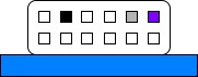
Now we can perform synthesis, implementation, and bitstream generation. Before we program the board we need to connect the UART. The speed is 19200, with 8 data bits, no parity, 1 stop bit, and no flow control. If using Basys 3, the UART is connected to connector JA in the following fashion (you may remember this picture from my earlier FPGA blog text where I connected Basys 3 to Raspberry Pi):
Now, if we proceed to program the board, we should receive the following message in the serial terminal:
NEORV32 Bootloader

BLDV: Apr 28 2025
HWV:  0x01110400
CLK:  0x05f5e100
MISA: 0x40801104
XISA: 0x00000083
SOC:  0x0003800d
IMEM: 0x00004000
DMEM: 0x00002000

Autoboot in 10s. Press any key to abort.
Wonderful! Press any key to stop the bootloader, and let’s compile a program from NEORV32 C samples that we can upload to the device to make the processor run a piece of compiled code.

Booting a C Program
For compiling the software, we need to have a cross-compilation toolchain that targets RISC-V. Chapter 1, Software Toolchain Setup, of the user guide covers the setup. I chose to build the toolchain myself and add it to PATH. As mentioned in the user guide, you can use make check command in one of the example projects to check that the toolchain is installed correctly:
cd sw/example/demo_blink_led
make check
As I built the toolchain myself, I had to edit RISCV_PREFIX in the makefile of the project. My prefix was riscv32-unknown-elf-, and setting the variable to that value fixed issues about the toolchain not being found.
Chapter 4, Application Program Compilation, of the user guide explains how to compile a sample software with the toolchain. sw/example directory contains samples, and as is the tradition, we will build the blinking LED example:
cd sw/example/demo_blink_led
make clean_all exe
That’s it. This will generate neorv32_exe.bin that is a binary suitable for use with the bootloader.
Sending the Binary to the Bootloader
Instructions for transferring the binary can be found in chapter 5 of the user guide. To summarise:
- In the serial terminal that is opened to the FPGA board, press
uwhen the bootloader is stopped to start waiting for the binary. - Send
neorv32_exe.binfile through the serial terminal as a raw binary. I recommend using TeraTerm for this as it was quite easy to get it working, just select “Send File” from the File menu and enable the “Binary” option to send it. “Sequential Read” also seemed to work better, so I recommend that as well. - Once the file is transferred, press
eto execute binary. - Enjoy the light show on your board, thanks to the wonderful C program.
Using Internal Memory of the CPU to Run Programs
Now, if you do not want to upload your binary to the board every time you reset it, you can also directly “install” it into the NEORV32’s internal instruction memory. Chapter 6 of the user guide, Installing an Executable Directly Into Memory, covers this. Simply put, you’ll want to run make install instead of make exe. This generates and installs neorv32_application_image.vhd file that is used to initialise the internal memory. Note that you need to disable the bootloader for this to work. I won’t be using this approach as it’s faster to run new software iterations using the bootloader, but I just wanted to let you know that this is an option.
Creating a Vivado Block Design
Now, if you intend to use the NEORV32 as a complete SoC, this kind of a setup is solid choice. It’s simple, and you can quite easily configure it from the top-level VHDL. However, if you plan to create something more complex or use the NEORV32 only as a CPU, it may be a good idea to try block design.
Block design is a higher-level design process where you use IP blocks to build the system. For example, you can add a processor block and connect it to memory blocks using bus lines to build a SoC. We are going to do more of that in the next FPGA blog text, but first, let’s create a simple block design that utilises just the NEORV32 IP core and the ports it connects to.
The block design is interesting in the sense that in some cases you won’t have to write VHDL at all. It is also a bit difficult to completely explain a block design in text format as it’s inherently quite visual, but I’ll try to include the relevant screenshots.
Packaging the NEORV32
The first thing to do is start a fresh project and then read more of the fabulous NEORV32 user guide, this time chapter 11, Packaging the Processor as Vivado IP Block. The instructions there list two options for running the packaging script, either using GUI or Tcl console. I couldn’t quite get the script working from GUI, IIRC some relative paths didn’t work correctly, so I was left with the Tcl console option.
In the console located at the bottom of the screen, I navigated to the neorv32/rtl/system_integration directory and ran source neorv32_vivado_ip.tcl. The instructions mentioned that a second Vivado instance would open, which did, and then close, which didn’t happen for me, so pay attention to which Vivado instance you’ll continue working on. Other than that, it worked nicely.
The next thing was adding the custom IP repository to the project. This could be achieved by choosing “Settings” in the Project Manager, usually located on the left side of the screen, then navigating to Project Settings -> IP -> Repository, clicking the plus, and selecting neorv32/rtl/system_integration/neorv32_vivado_ip_work/packaged_ip directory.
Getting Started with the Block Design
To get started with the block design, choose “Create Block Design” from the Project Manager. This should open a blank canvas on which you can paint your digital design. You can add new IP blocks by using the plus icon at the top, define ports by right-clicking on an empty space and selecting “Create Port”, and connections are simply created by dragging from one port to another. First, add the NEORV32 block to your design using the plus icon.
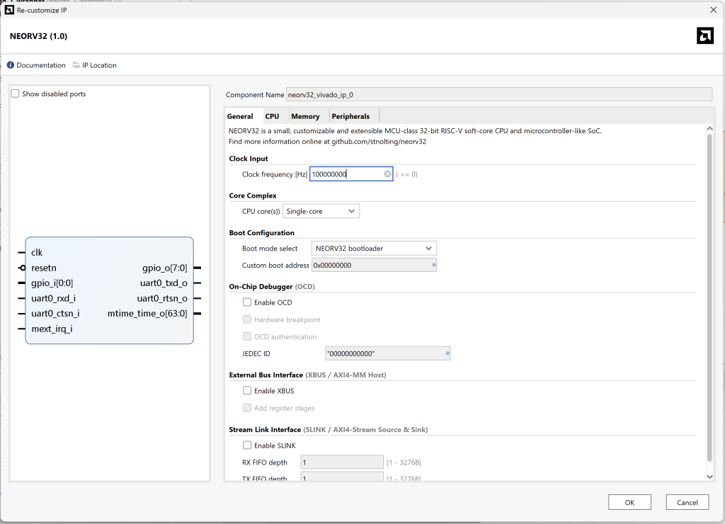
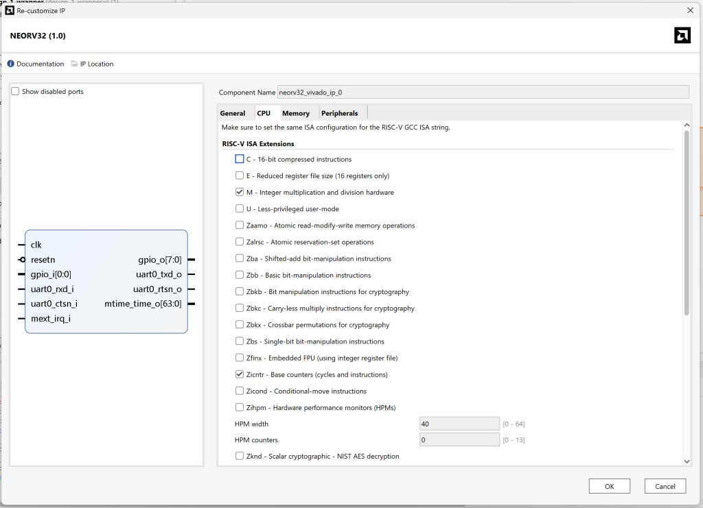
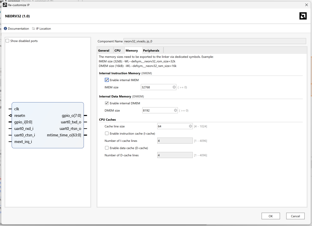
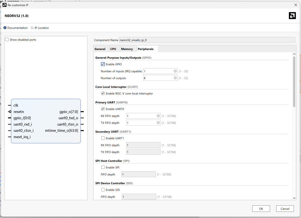
Double-clicking the NEORV32 block allows us to configure it via GUI. From the settings, check that we are going to be using the bootloader, UART, and 8 GPIOs (for LEDs). Also, for Zephyr, we need to enable the core local interruptor, M & Zicntr instruction set architecture extensions, and also we need to increase the size of the internal instruction memory to fit the RTOS into it. The following screenshots display the relevant parts of the configuration (the rest can be left to defaults):
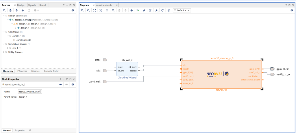
Once that is done, add a Clocking Wizard to your design for clocks and reset (I didn’t need to configure this block further), and add the ports by right-clicking the canvas. Note that the gpio_o port should be a port vector because there are 8 LEDs. The result should look something like this:
Before generating bitstream, we need to do two things: create the constraints file, and set the block design as top. Adding the constraints file should be quite familiar at this stage, and you can use the constraints file from before. To set the block design as top, right-click the block design .bd file in the Sources tab, select “Create HDL Wrapper”, and wait for a moment. The wrapper usually gets automatically selected as top, but in case it doesn’t right-click on the wrapper and select “Set as Top”.
Now you should be able to generate the bitstream as before and program the device. This should still result in a similar bootloader output as before, and you should still be able to upload the binary to the board to enjoy the magnificent LED show. Congrats, we achieved the same thing as before, but in a slightly easier way (or at least in a way that involves less VHDL).

Building Zephyr for NEORV32
Let’s move on to the RTOS side. As mentioned in the background information, Zephyr RTOS has support for NEORV32, so most of the heavy work has already been done for us. Again, we’re mostly left with the light burden of reading the documentation. The support is not 100% complete, but it is complete enough so that we can run the Zephyr blinky demo on our board. To get started, we follow Zephyr’s Getting Started guide up to the “Build the Blinky Sample” section. At that point, we need to make some modifications.
Customising the Board
Zephyr has two NEORV32 boards available: minimalboot and up5kdemo. We will customise the minimalboot board for our custom device. The device tree source for the board can be found from zephyr/boards/others/neorv32/neorv32_neorv32_minimalboot.dts. From there, we want to locate imem and dmem nodes to set up the memory sizes. If you recall the CPU configuration screenshots earlier, we set these to 32KB and 8KB. In addition, we’ll set up ngpios in gpio node to 8 (we will only use GPIO outputs). Patch with content like this should get you started:
This should be enough to boot the board. You should now be able to continue with the Getting Started guide and use the neorv32/neorv32/minimalboot as the target board for blinky:
west build -p always -b neorv32/neorv32/minimalboot samples/basic/blinkyIf you want to know a bit better how the device tree is defined, you can go through neorv32.dtsi as well. It is basically the top-level definition file for the SoC, and the board-specific files enable features from this include file.
Building the NEORV32 Image
We’re getting close to running Zephyr on NEORV32 already. If you followed the Zephyr guide, we now have produced a file that can be flashed with JTAG. However, if you remember the block design from earlier, we don’t have the on-chip debugger enabled. Therefore, we need to build a binary similar to the neorv32_exe.bin that can be used with the bootloader. To do that, we need to ensure that the image_gen binary from the NEORV32 repository is in PATH. This information is also mentioned in the NEORV32 page of the Zephyr documentation.
If you built the C code example from before, the image_gen binary should be available in neorv32/sw/image_gen. If you did not build the example, then please do. After you’ve verified that there is an image_gen binary in the directory, you can add it to your path and rebuild the Zephyr image. Once the build completes, you should have build/zephyr/zephyr_exe.bin binary available. Boot the FPGA board once more, and this time upload the zephyr_exe.bin binary to it instead. Executing it should result in a different kind of light show (much more boring one) and the following message in the serial terminal:
*** Booting Zephyr OS build v4.1.0-3787-ga6ab43aa888b ***
LED state: OFF
LED state: ON
LED state: OFF
Conclusion
Phew, that was a lot of effort to blink LEDs. But this serves as a solid foundation for the next text where we create a more complex SoC that utilises SPI input to generate an RTOS interrupt (spoiler alert). If you have questions, please ask. I know this text was quite a high-level explanation of a deeply technical topic, but with trial, error, and some fooling around in Vivado, these concepts become familiar quickly. Thanks for reading.
Recommended Reading
- NEORV32 User Guide and Datasheet: Yes, I still recommend reading these
- Zephyr NEORV32 page: This page contains plenty of information for running Zephyr on NEORV32 and how to customise the board even further.
- RISC-V Wikipedia article: I have not read this in its entirety, but understanding the basics and ISA extensions is useful.
- Real-time operating system Wikipedia article: I know using Wikipedia as a source is frowned upon, but it just tends to be a good source for high-level overviews.